
The
year started off with a very productive weekend.
The Terry House was very full, due to the
fact that this weekend was also a MSR&LHA Board meeting
weekend, which we
normally try to avoid. If
there had been
more people on Friday night, some of us were going to be FORCED to
sleep in a
CABOOSE parked in front of the depot that was all decked out with
Christmas
lights.
Some
of us were disappointed that a few more did not show
up.
The
following report will bring things up to date, but this
is not to imply that all work discussed was completed this particular
weekend.
LOCOMOTIVE FRAME
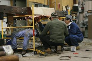
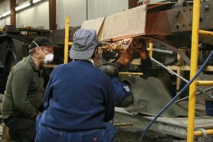
The back end of the deteriorated frame has been prepared for weld repairs. The flanges of the frame channels were wasted to sharp knife-like points, instead of being rounded, due to being worked on by acid and moisture for almost ninety years. The old flanges were removed by cutting the old flanges off with four inch diameter "zip wheels" powered by a hand held grinder unit.
  Working under the lomotive frame to cut away badly deteriorated parts of the frame. This was difficult and tedious work despite being able to lay down on the job. (Photos by Walter Scriptunas II). |
Removing
the upper flanges was not fun, but working on the
bottom side of the frame was pure torture, and nothing but drudgery. A scaffold plank was placed
under the frame so
that the operator of the grinder could lay on his back,
reach up with the grinder, and
judiciously grind along a line carefully
scribed on the
bottom of the frame for guidance.
Try working on one's back with your arms up in the air for hours at a
time. This process
went on for several
weekends, all day long.
The
worst part of the job was the grinding debris: steel
slivers, rust chunks, and grinding wheel chunks that were continually
trying to
get into one's eyes, ears, shirt, and regions lower!
It was found very quickly that common face
shields were useless on this job.
The
solution to the problem was for the lucky grinder operator to recline,
and don
the welder's face shield with a clear lens.
This garb was in turn draped by a 2 by 3 foot piece of
fireproof canvas
with a small rectangular opening cut into it to fit over the lens
opening of
the face shield. The
operator then
reached up and around the canvass, and grasping the grinder, went to
work, but
for not long periods without interruption as moisture from breathing
would coat
the inside of the clear lens, and make seeing where to cut impossible. With luck, two
or three wheels could be
destroyed before the operator would have to roll out from under the
frame,
clean the hood (both internally and externally), clean his face,
eyebrows,
ears, and shirt collar. This
process was
repeated over and over and over, seemingly without end.
In
removing in excess of 80 lineal feet of wasted flanges,
close to 100 zip wheels were consumed, at a cost of close to three
bucks each.
The
person grinding was supported by two very necessary
helpers: one person
to maneuver the
trouble-light and drape the canvass, and another person to keep new zip
wheels
on the three grinders that were being used, and feed these to the
operator. Wheels
lasted less than five
minutes each, but in this time the grinder motors would become very
hot,
necessitating the use of three grinders to allow for cool-down time.
HORN/PINION GEAR COMBINATION
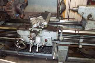
 Lathe with gear mounting. This arrangement allows the gear to be removed without damage by machining away the shaft. (Photo by Byron Waltham) |
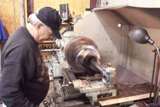
 Lou Aprile operating the lathe to cut out the center chaft from the horn gear. (Photo by Byrom Waltham) |
CENTER (SWIVEL) PLATES
The center or swivel plates are the pieces that attach to the truck and frame bolsters, and act as bearings between the trucks and locomotive frame. The trucks must pivot as the track structure under the locomotive changes direction, which was quite often on a logging road, or the locomotive will jump the track. With our Climax having logged more than 330,000 miles in its life, one can guess that all six swivel plates, three male and three female, are shot beyond repair. To keep costs down, it was decided to hog the new parts out of large pieces of 3½ and 4 inch thick rectangular plates. To this end, one volunteer roughed out the 1-inch deep recess that allows the swivel plate to straddle the bolster. The trash can of shavings from this process was very heavy.MISCELLANEOUS
We are running out of storage room in the shop, and quite some time was spent shifting things about in order to create more useable space. An example was the placing of an entire pallet load of boiler lagging material onto overhead shelving for long-term storage.UPCOMING
The priming/painting of the completed coal bunker must be finished so that it can be moved outside for long-term storage. This important job must be done as quickly as possible in order to create room for the assembly of the tender tank, which has a 9’-4” square footprint, and will scale at about 3-tons.