MSR&LHA color logo

Climax Restoration Project

Summary of the March 17-18, 2007 Work Session

Another great weekend. Several different projects were worked on, and we picked up one new volunteer (a young one at that, which is important if the rail preservation field is to survive beyond us gray-heads) that says he will return and bring his older brother. Maybe he enjoyed himself, or possibly it was the food. The bill-of-fare for Saturday evening: fried chicken with milk gravy, mashed potatoes, peas, and Cole slaw. Dessert was not needed.


Horn Welding (Buildup)  and Machining

A welder/helper team built up two complete sets of horns Saturday. The team effort made rather simple work of the job. The welder burned a rod, then stepped out of the way while the helper cleaned the flux form the just-applied bead of weld. While the helper was doing his task, the welder installed another electrode into the holder, and was ready to weld the instant the helper stepped out of the way.

 The horns were worn so oval, a few beads of weld were applied along the axis of the horns to return them more closely to the round shape. This decreased the amount of concentration required for the welder to end up with a piece that would "clean up" the first time it was machined upon in the lathe. These beads were done with the casting laying flat on the bench. All other welding was done with the horns held vertically in a home-made positioner. Welding started at the outer bottom of the horn, and spiraled around, and around, and around...until the top was reached.

Turning the welded horns was done in the old 20 inch Lodge and Shipley lathe, due to its large swing capability. A very crude drive arm was bolted to the chuck wheel to power the work piece, which was held between centers. The horns finish at 2.250 inch diameter. Due to the out-of-balance nature of the part, all machining was done very slowly, about 15-20 RPM.
See Andy Fitzgibbon's posting on the Practicalmachinist.com Web site for photos of this process.

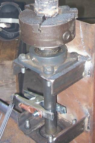
Welding fixture made from scrap parts
The scrap box welding fixture. Made from old bearings, a junk lathe chuck, and scrap steel. It can  be mounted horizontally or vertically, as the case requires. Note the ground cable clamped on to rotating shaft. A lazy welder simply stands in one spot and rotates the work as welding progresses. No more playing "chase the welding rod".  (Photo by Grady Smith).

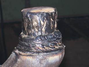
Partially built-up horn
A very ugly horn partially built up with weld.  The purpose of the vertical beads were to transform a very oval horn into an approximate circle before building up the entire circumference of the item to assure that the piece would really have adequate material applied in the right places to machine completely.  This machinist/welder only likes to build up parts once!  (Photo by Grady Smith).
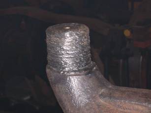
Built-up horn ready for machining
A completely built-up horn. The machined diameter will be 2.5 inches. This may or may not be the same horn as the one above. (Photo by Grady Smith).


Square Shafts

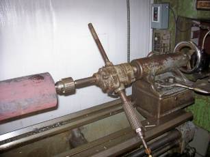
All lathe work on the shorter of the new square shafts was completed. The portion that is to go into the socket of the horn casting was machined for a 0.006 to 0.007 inch interference, shrink fit. At assembly, the horn casting will be heated several hundred degrees to expand the socket to the point that it can be simply slipped over the shaft without pressing or pounding. After cooling, it will stay wherever it is until something breaks. Having a shrink fit situation go sour part way on is not a pleasant happening. Lathe work on the second, longer shaft was started. After the rough forging was blocked up on the tailstock end, an air motor was used to drill the center hole. As can be seen in the photo, the drilling of this hole, on this lathe anyway, would have been difficult if the forging had been much longer.
Drilling the end of the second square shaft
If the piece had been much longer, we would have been in trouble.  Note the tailstock of the lathe hanging out past the end of the lathe bed.  (Photo by Grady Smith).


Drawbar Pocket


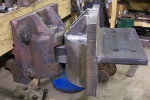
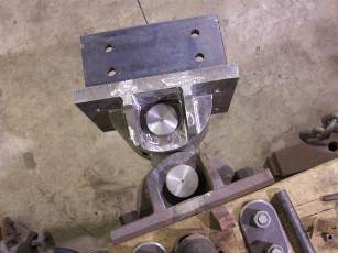
More welding was done, and the end is in sight for this part. The two top reinforcement gussets were welded into place, and the welds ground to mimic fillets of a casting. After all the welding is completed, and the sharp corners removed from the entire fabrication, all visible portions of the unit will be heavily needle scaled, giving it a peined look, to texture the surface to give it the "sand cast" look. Though the drawbar pocket is not yet completed, the urge to slide it onto the drawbar was too great to resist. See photos for the results.   (See the before and after photos at the bottom of this page).

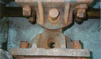
Old draw-bar pocket
Side view of mismatched draw-bar pocket arrangement prior to the locomotive being dismantled. Left pocket is not original to the locomotive and has been replaced.  (Photo by Chad Thompson).

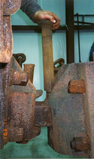
Almost completed draw-bar pocket in place
Side view of the almost completed draw-bar pocket, showing it temporarily in place against its mate.  (Photo by Grady Smith).
Old worn draw-bar pocket
Top view of the old draw-bar pocket.  Note the oval hole in the pocket.  Six inches of slack was present in this assembly prior to rebuilding/replacement of all the various components: both pockets, both pins, and the draw-bar. (Photo by Chad Thompson
Top view of the new draw-bar pocket
Top view of draw-bar arrangement, showing the far range of its motion.  (Photo by Grady Smith).


Remodeling of the Storage Locker

One volunteer spent a great portion of the weekend improving space in one of the storage lockers to better accommodate and organize our growing tool inventory. This is a pretty big job, and if there are any carpenters out there, extra help sure would be nice.


Main Frame Repair

All eroded flanges on the top of the frame members have been removed. This was a dirty, gritty grinding job, but fun compared to the next part of the task: doing the same thing to the bottom side of the frame. A hint: the thing is too heavy to turn over.

Return to the Climax Restoration Project page

Return to the MSR&LHA Home page

Page last updated or validated on November 28, 2008