MSR&LHA color logo

Climax Restoration Project

Summary of the February 17-18, 2007 Work Session

After a month off due to bad weather it was good to be back at work on the locomotive. Eight volunteers came form as far as Erie, PA, and North Carolina, even with the predictions of more snow.

Several projects are currently underway.

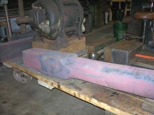
Unmachined square shaft
As-delivered forgings to be machined to replace the old , worn, and severely rusted square shafts of undetermined age and soundness that were on the locomotive at the beginning of the project.  The square portion will finish at 4 3/4 inch;  the round section at 4 1/2 inch.  (Photo by Grady Smith).
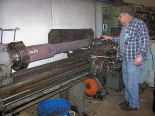
Initial square shaft cut
Dave Arthur ready to take the initial cut on the round section of the shorter of the two new square shaft forgings, in the newly donated and activated Reed-Prentice engine lathe.  (Photo by Grady Smith).
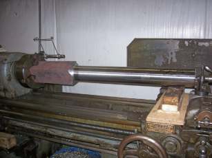
Final square shaft diameter
Three cuts have been made on the short forging , and the diameter is within 1/10th of an inch of the finished size.  Wooden blocks under the right end of the stock will support the weight of the piece for two weeks, until the next work session. The tailstock spindle has been retracted from the work slightly, to prevent the ball bearing center from taking a "set," or warping from being strained in one direction (down) for a long period of time.    (Photo by Grady Smith).
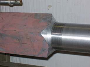
Rough cut of square shaft transition
The rough-stepped transition from round to square.  This will be a smooth curve on the finished piece, and will reduce the likelihood of the forging  breaking at this point. (Photo by Grady Smith).

Crankshaft

The large 8.5 inch diameter bar forging has been rough turned to about 6.5 inches.  This is as far as it will be taken down until the old crankshaft assembly has been pressed apart.  Until the size and condition of the crankshaft-gear hub has been determined, the prudent thing to do is have patience.  With $3,000 worth of steel hanging in the balance, knowing the final dimensions is very important.  


Horn Castings

Another horn casting was separated from its old shaft by drilling/boring/pressing it free.  This was the first horn that we have removed that did NOT have its old shaft swelled by cold chisel grooves.  The machinist that fit this horn evidently got the interference fit correct without cheating.

From the photos in the last installment, it was quite evident that the horns will need  to be built up and re-machined to new tolerance.  To make this welding job easier, we made a cheapo welding positioner out of used flange-mount pillow block bearings, a very old worn out lathe chuck, and a length of rusty 8 inch channel iron.  Maybe we can get a picture of this work of art that will also show how it is to be utilized.
 

Reed Prentice Lathe

The mounting of the 12-inch four-jaw chuck was completed, and a test piece was turned on Saturday.  See draw-bar pins for details
 

Draw-Bar Pins

The main locomotive frame and the auxiliary tank frame are linked together by a 4-inch by 6-inch chunk of steel called a draw-bar. Both ends of the draw-bar are secured by 2 5/8 inch diameter pins, with heads on the top ends to prevent them from falling out.   

These pins were turned this weekend, from material (most likely 1045 carbon steel) salvaged from the old square shafts that we are replacing.  One pin was machined entirely by a beginning lathe hand that had never operated an engine lathe, or any other machine tool.  The second pin was turned by a very seasoned machinist as a test piece to evaluate our just-up-and-running Reed Prentice lathe. The guy says that there is something badly wrong with the lathe, but that he will gladly buy it.  Don’t believe even one word of
his evaluation, as he has an identical lathe in his garage at home! 
 

Square Shafts

The forgings for the new square shafts are in hand in the restoration shop. The forge shop completed and had them ready for pickup in less than three weeks from the day they were ordered.  They were quite a load for a Toyota pickup, but it rode quite smoothly. 

As-forged dimensions are:  approximately 5 1/4 inch square by 17 inches long on the square portion, and  5 ¼ inch diameter along the rest of their length.  The squares will finish at 4 ¾ and the rounds at 4 ½ inch.

Sunday morning the shorter of the two forgings was mounted in the lathe, and the round section was roughed to within 1/10th of an inch of the finish size.  Three cuts were required to “clean up” the round area.  After adjusting the tailstock alignment just once,  the lathe was cutting only 0.005 inch taper  in about three feet.   NASA would not approve, but this is not at all shabby considering the function of the part.   

The transition from round to square at this point is just roughed in as a series of steps.  When the turning is finished, the transition will be a smooth curve, turned with a very simple home-made radius turning attachment that will be clamped into the toolpost. 

Andy Fitzgibbon has posted several more photos on the Practical Machinist Web page at practicalmachinist.com.  


Return to the Climax Restoration Project page

Return to the MSR&LHA Home page

Page last updated or validated on November 28, 2008