MSR&LHA color logo

Climax Restoration Project

Summary of the January 20-21, 2007 Work Session

Saturday was a long and very productive day, with work being done on the locomotive main frame, tender frame, square shafts and horns, coal bunker, and the articulation joint between the main/tender frame. For the first time in several years, the work session was cut a bit short Sunday on the account of snow.  Flurries started  before 8:00 AM.  The snow accumulated quite quickly, and slick mountain roads are nothing to trifle with.  The last person departed from Cass at 11:20 AM.  All participants had snowy and slick drives home, but everyone did arrive home safely.


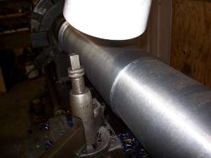
Crankshaft on the lathe
Work continued on reducing the diameter of the crankshaft from 8.5" to about 6.5".  This photo shows the depth of a typical cut, about 1/4".  (Photo by Grady Smith).


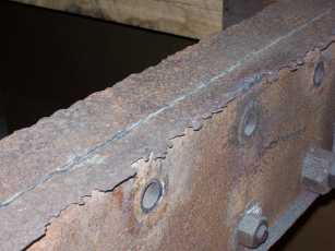
Deteriorated main frame flanges
This is what the flanges of the main frame's "C" channels look like.  They are severely deteriorated and must be replaced.  (Photo by Grady Smith).

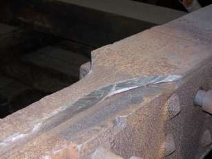
Main frame after upper flange removal
This view shows the main frame after the bad flanges were cut away.  Each cut was almost 10 feet long and took about five hours.  There are two more upper flanges to be cut off and four lower flanges (that will be much harder to cut).   (Photo by Grady Smith).


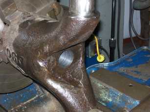
Horn mounted in lathe for drilling
A horn (or trunnion) mounted in the lathe so the shaft can be partially drilled out.  A small pilot hole was drilled, then followed by the larger hole shown above.  This hole was then bored out until it reached the keyway and allowed the old shaft to be removed. (Photo by Grady Smith).


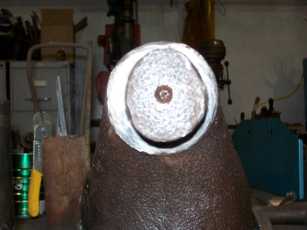
Severely worn Horn shaft
End view of a horn showing the severe shaft wear.  The worn shafts will be welded up and machined back to the correct round diameter.  (Photo by Grady Smith).


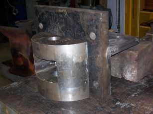
Partially completed new articulation joint
View of the partially completed articulation joint.  The original was trashed in a smashup that ruined the tank frame.  Its replacement was not a match for the half of the joint that evidently was not broken.  This new fabrication matches the original..  (Photo by Grady Smith).

Crankshaft

Lathe work continued in the reduction of the large shaft purchased for the manufacturing of the new crankshaft.  Several hundred pounds of blue shavings were produced, and hauled out to the scrap dumpster.


Tank Frame

Major work on the tank frame construction was pretty much completed.  The last four, of approximately twenty-six, tapered body-fit bolts were lathe-tapered to fit into their respective taper-reamed holes.  These last four bolts fasten the four diagonal draw head braces to the longitudinal side beams.

Though the heavy metal work on the tank frame is complete, the entire unit is far from finished.  Painting, installing wooden decking, and hanging of air and water lines remains to be done, along with lots of small details, that cannot be added until much later in the assembly process of the locomotive.


Main Frame

The main frame of a Climax 70-ton locomotive was a pair of fabricated 8-inch beams, built by placing two "C" channels back-to-back, and riveting them together to form an "I"  shaped beam, with stiffeners nested down into the "C's".  The flanges of these beams have, in high-acid areas such as under the coal bunker, rotted almost  to nothingness.  New flanges, cut from new channels, will be welded on to replace these wasted  elements.   This weekend some of the rotted flanges on the top of the frame were removed by using many thin (1/16 inch) cut-off wheels, one at a time, on a four inch hand held grinder.   The process was fairly simple: scribe a line where the cut is to be made, then follow it with the grinding wheel, all the while being sure to keep the "zip" wheel oriented straight up.  Eventually the wheels cut deep enough to sever the flange from the rest of the beam. Doesn't sound too bad, you think?  Better guess again: this is a filthy, gritty, nasty job, but the man who did it all day did not complain once. But think, the top side was the fun side to do.  The bottom has yet to be tackled.  Won't working laying down, looking and reaching up be fun?

As a point of interest, these thin cut-off wheels do not last very long, probably less than five minutes of continuous grinding.  Our stock of one hundred wheels will not be enough to come close to finishing the job. Their cost each?  About $1.70.


Square Drive Shafts

This locomotive has three square drive shafts that enable the drive line assembly to automatically adjust for constantly varying length requirements as the locomotive's trucks swivel to conform to the irregularities of the track they are riding upon.  Two of these are rather long, about 48 and 67 inches  long.  One end of each shaft, is hammered and machined to form a 4.5 inch square about 14 inches long; the remainder of each shaft is rough forged to about 4.5 inch round.  On the very end of the round portion on each shaft is fastened a "horn casting," a part of a "ring-coupling" assembly, known to modern mechanics as a universal joint.   

When the restoration began, the intention was to rebuild these shafts, but re-examination of the parts and issues involved were cause for a change in strategy: make them new. Do not waste valuable time on the old ones that would still be junk, but good looking junk, even after reworking.   What were the issues?

1. The old pieces are worn and corroded way under their original size.  To weld each one up large enough to finish machine at 4.75 inch would take approximately 40-50- hours. Then there is the time required to machine the welds to size.

2. The horn castings need to be removed, rotated 45 degrees to align with the corners of the square end (explanation to follow) and somehow re-attached.  This process, in one way or another, entails welding upon the round end of each shaft, which again translates into many hours of welding and machining.

3. The age and wear upon these parts indicate that fatigue may be a factor in their soundness, even before any welding is done upon them.  Welding on these parts will not improve their soundness one bit.

4. The intent of this restoration is to out-shop a locomotive that is to be a reliable unit of motive power, capable of continual use, hopefully without major break downs (but this can never be 100% guaranteed, of course)  for many years to come. 

When these four issues are evaluated, it only makes sense to go with new parts: forgings can be obtained at reasonable cost, volunteer hours will not be potentially wasted, and a more assuredly reliable locomotive will be the result. As we are going to make new square shafts, the horns attached to them needed to be salvaged for rebuilding.  The first operation, after specking out the shafts, was to saw the horns free, about two inches from the hub of the casting.  secondly, the horn was chucked in the lathe, and the center of the shaft drilled out.  This small hole was then drilled and bored out until the boring operation was removing a portion of the drive key. With the bottom of the key exposed, the key could then be driven out, as it was no longer held captive on all four sides.  The horn was then taken to the big Cass shop, and the remaining relaxed portion of the old shaft was pressed out.

Eventually the horns will be welded up oversized, and machined to original dimension.  With this in mind, the external rust and corruption in the zone to be welded was removed by grinding.  Not really pretty, but effective.  We learned on the first horn that we did that bronze from the horn bearings was embedded into the surface of the metal: the preheating flame burned with an odd green color, the sure sign of copper contamination, which makes for a very poor weld.

If one is wondering why go to the great lengths rotate the horns 45 degrees to align with the diagonals, or corners, instead of the flats, here is a simplified explanation: for universal joints to operate reasonably smoothly, they must be assembled as TIMED pairs. TIMED in this case reefers to the parallelism of the horns from one end of the shaft to the other. 

In a truck or automobile this translates to the two "+" shaped crosses being parallel to one another. The modern slip joint in the drive shaft controls the relative radial positioning of these two components by the means of closely spaced "splines", that can be pulled apart, rotated slightly, and reassembled.  BUT, there is only one position, out of say thirteen splines, that provides the exact and proper alignment of the crosses along the length of the drive shaft.  If a drive shaft in an auto is assembled even one spline out of alignment, an observant driver will know things are not just right: the drive shaft will vibrate and will not be quiet.  The farther the crosses or horns are out of sync with each other, the more the vibration and noise increase. 

What has this to do with a Climax Locomotive?  The horns of a Climax ring coupling are 45 degrees out of sync, the worst possible condition. As a horn is rotated beyond 45 degrees, the offending horn begins to approach the next horn at LESS than 45 degrees.  For whatever reason, the horns on a Climax drive shaft align with the FLATS of the male members, and the horns of the female members align with the diagonals of the squares, and no matter how they are assembled, they will always be 45 degrees out of TIME.  This is possibly the roughest running universal system ever constructed.  The vibrations set up by this system is destructive of all the components of the entire drive system, from the crankshaft all the way through to the final drive gears.  We can correct this condition by manufacturing new square shafts, and properly position the horns relative to the squares.                  


Articulation Joint

For a long while we have been working to fabricate a new half of the hinge, or articulation joint that connects the tender frame to the main frame.  The locomotive operated for many years with hinge halves that were not really mates for each other, and resulted in excessive damage due to misalignment and overriding.  This weekend welding together of the several parts began. Several more weekends of welding remain. 

If you are a proficient welder, this project needs you.


Return to the Climax Restoration Project page

Return to the MSR&LHA Home page

Page last updated or validated on November 28, 2008