This
first work session of 2007 was very well attended by eleven volunteers
who were kept busy from early morning until late Saturday evening, and
until well after noon Sunday. There was activity on several
areas, some machine-tool related, some locomotive related.
Donated Machine
Tools: Radial Drill
Press
One three-member family team from Maryland
left home at 6:00
AM to
pickup a rather large radial drilling machine being donated to the
Association by a company in Bridgewater, Virginia. The
top-heavy
machine was quite heavy, and they arrived in Cass about 2:00 PM, after
a very slow trip.
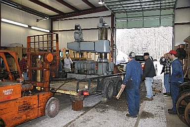
The
radial drill press
as it was being unloaded from its delivery trailer.
Unloading was not trivial since the small fork lift could not
get good access to the press on the trailer. (Photo by Water
Scriptunas, II).
Unloading the machine
was quite an ordeal. During the loading process,
to balance the weight of the machine properly on the trailer, a quite
large fork truck had been used to push it to the middle of the
trailer. At Cass only a 8,000 pound capacity lift was
available
for the unloading process. There was no way that this
lift’s stubby forks could reach the machine from the rear of
the
trailer, so our only recourse was to slide the drilling machine to the
very back edge of the trailer. The first act of unloading was
to
block up the rear corners of the trailer so that the weight of the
heavy drill would not flip the pick-up attached to the front of the
trailer.
Next the fork lift was chained to the
drill to see if it
could be
simply pulled to the back edge of the trailer. NOT!
The
trailer scooted, but the machine stayed put on the deck. The
solution was to have five stout guys with pinch bars put a strain on
the drill, and then have the lift operator drag the offending machine,
little-by-little, to the rear of the trailer deck. From there
it
was a rather simple matter to pick the machine up for unloading and
eventual final placement in the shop.
Our old radial drill
(three foot arm, #4 MT spindle) was
moved out of
the way to make room for the newly arrived machine (five foot arm, #5
MT spindle). Before the day was over the new machine was
leveled,
and wired. After some initial fuse problems, how to run it was figured
out. Sunday a few members cleaned and oiled all the external sliding
members of the machine, and checked all fluid levels in the various
gear boxes. After we buy a few fuses, we will be ready to make
holes.
Donated
Machine Tools: Engine Lathe
On another machinery matter, our newly
donated Reed Prentice
18 by 84
inch engine lathe received some attention. New plastic was
applied to three oil-level ports, and oil was added to bring the levels
up to the proper levels. The machine was leveled
end-to-end
and front-to-back. A brand new L1 backing plate was attached
to
the headstock spindle in preparation of machining it to fit the back of
a nice 12 inch four-jaw chuck, which will be done as soon as the
machine is wired. The electrical conduit was run from the
breaker
panel to the machine, but no #6 wire was on hand to complete the
job. This task most likely will be finished at the next work
session, January 20-21.
Smoke Box Saddle
Repairs
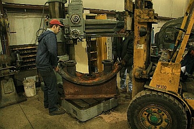
The
rebuilt smoke box saddle being placed on the bed of the
recently installed radial drill press, where six broken studs will be
drilled out. (Photo by Water
Scriptunas, II).
The poor old smoke
box saddle casting was in terrible shape, due to the
fact that it operated in a high acid/temperature atmosphere its whole
working life, and then sat open to the elements of nature for thirty
years after the Cass shop fire, in 1972.
The two flanged stand pipes that the "Y"
pipe fastens to were
eroded,
corroded, and cracked beyond salvage. In fact, the bases of
both
stand pipes had been half way repaired by brazing, sometime in the past
before the locomotive was removed from service in 1959. The solution to
these problems was to make a pattern, cast two new flanged tubes, and
Oxy-acetylene cast-iron weld them to the otherwise structurally sound
smoke box casting. As yet, the bolt holes in the new stand pipes have
not been drilled or tapped for studs. This can only be done
after
the new "Y" pipe has been fabricated.
The saddle casting was returned to Cass on
the trailer along
with the
radial drill. After the saddle was unloaded, the haulers
removed
all but six severely deteriorated studs, without breaking any off, and
without stripping the threads in any hole. Good fortune was
smiling on them. The remaining six studs are the
ones that
hold the exhaust nozzle in place, and are located right smack
dab
in the middle of the top of the thing. These studs are broken
flush with the surface of the casting, so they will need to be
carefully drilled out... not a fast job for someone with little or no
patience. This will be a great job for the new
radial
drilling machine. In fact, the saddle has already been set onto the
drill for doing this very job.
Locomotive Crankshaft Lathe Work
The
crankshaft of a Climax locomotive is a built-up
unit….basically a machined central shaft with a pressed-on
gear in the middle, and crank discs pressed onto each end.
The
crankshaft of Climax CN 1551 has been condemned by the project manager
because of the discovery of undercut welds holding the
central gear in place. To weld on such a piece is very
suspect: non-heat treated welds on heavily stressed shafts will
eventually be the cause of the shaft’s structural
failure. Shafts such as this never break when setting still.
Things always come unglued at the worst possible time, such as when the
locomotive is working to the maximum on the final grade to Bald
Knob. If this crankshaft would break in such circumstances,
the collateral damage to surrounding engine components could be
devastating. This, in a nutshell, is the reason for scrapping
the old crankshaft.
The only two possible reasons
for these welds to be on the shaft in the first place are 1) to keep
the gear from migrating: or 2) to keep the gear from migrating
FARTHER. Upon close examination, the latter reason seems to
be the case. When looking very closely at the area adjacent
to the gear hub, two distinctly different degrees of corrosion are
present, as if an area about 3/8 inch wide was not always exposed, and
thusly corroded to a lesser degree than the rest of the
shaft. The best guess is that the gear has indeed migrated.
Why
worry about the gear being a little out of place? The
crankshaft gear has migrated AWAY from its mate. This means
that the meshing gears are not engaging as deeply as they are supposed
to. Translation? Excessive, and premature gear wear.
The
fact that the gear moved in the first place means that the gear was/is
too loose on the shaft to stay put. What is the solution?
Make the fit between the shaft and gear tighter. Either
somehow shrink the hole in the gear, or produce a new shaft slightly
larger than the present shaft, so that many tons of pressure are needed
to assemble the pieces in a condition that is known as “an
interference fit”. In other words, shove a big pin
into a littler hole.
Until
the present shaft is removed from the offending gear and end-plates, it
is not possible to state what the diameter of the to-be-machined
crankshaft will be in the area of “the
fit”. There is a great chance that the gear hub
will need to be slightly bored oversize, to ensure that it is both
smooth and round. This very situation was encountered during
the machining of one of our new locomotive axles. One of the
axle gear carriers was discovered to have a scored and gaulded bore
that we chose to machine out to a new and true surface prior to
machining the axle to its press-fit diameter.
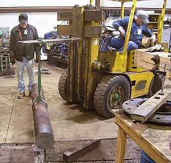
Lifiting
the new crankshaft in preparation for placing it in the Loge and
Shipley lathe. (photo by Andy Fitzgibbon).
The
steel for the new crankshaft was purchased from Ellwood Crankshaft and
Machine, Ellwood City, Pennsylvania. This firm made the new
crankshaft for Shay 11, and recommended that we use alloy steel 4130,
heat treated for the new Climax crankshaft. A bar 6 3/8 inch
diameter would have been sufficiently large enough to make the shaft,
but the smallest Ellwood stocks is 8.5 inch diameter, better than two
inches oversized! Enough material to make the main shaft,
plus the two crankpins, cost $3,000, delivered to Cass.
Ellwood explained that it would be financially better for us to turn
this shaft down to make the piece, if we have a lathe big enough,
rather than to pay them thousands of extra dollars to forge and heat
treat a one-of shaft of the requested smaller size.
This
weekend our too big shaft was chucked in our antique lathe, and the
production of hundreds of pounds of useless shavings began.
The 1,300 pound rough turned steel shaft was maneuvered into the 20
inch
Lodge and Shipley engine lathe with the fork truck. One end
of the piece was grasped by the four-jaw lathe chuck, and indicated for
being centered in the machine. The tailstock end of the piece
was temporarily supported by a steady rest large enough to easily
swallow the 8.5 inch shaft. Next the tailstock spindle was
moved very close to, but not touching the work piece. The
adjusting screws of the steady rest were then used as jacks to shift
the end of the rough shaft, measuring with a six inch scale to average
out tailstock spindle/shaft offsets at 3, 6, 9, and 12
o’clock positions. Once the shaft was
centered on the tailstock spindle, a tailstock center was installed
into the spindle, and used to lightly mark the center of the
shaft. This mark is where we drilled the 60 degree
countersunk “center hole” , by using an
air-powered drill motor to spin the bit. The drill motor was
guided and pushed into the work using the lathe tailstock.
Normally the work piece rotates to do this task, but in this
case, with so much heat treat scale and shaft weight
involved, rolling of the shaft would have injured the jaws
severely.
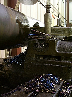
Cuttings
produced as the diameter of the crankshaft was cut down from 8.5" to
7.5". The final diameter will be about 6.3", but the
intermediate
size will allow use of an additional steady rest. (Photo by
Andy
Fitzgibbon).
Once the center hole
was drilled, and this
end of the shaft supported by the tailstock spindle, the big steady was
removed so that metal removal could begin. The game plan was
to reduce the right hand end of the shaft to a diameter small enough
that our smaller steady, about 7.5 inches, could be used to help
support the work. For a long while we experimented with
various feeds (rate of tool movement per rotation), speeds
(RPM), and depth of cut. After a while it was
determined how hard we could push the old lathe before chatter would
occur. Once the end of the piece was reduced in diameter
small enough for the smaller steady rest to be applied, the strength of
the machine setup increased by a great deal. We found that we
could push the machine to take deeper cuts, at more
RPM’s. Eventually we were taking cuts 3/8
inch deep, and reducing the diameter of the stock by 3/4 inch per
pass. The shavings were peeling off, like tightly coiled
springs about three inches long, and turning metallic blue by the time
they landed on the floor. Pretty impressive cutting for a
lathe approaching its 94th birthday. A few weekends of this
type of rough turning will get the shaft relatively close to its
finished size.
This process will continue at the
next work session, scheduled for January 20-21,
2007. New volunteers are always welcomed.
If you are interested in getting involved please check the
"Getting Involved" section on the Climax
Restoration Project page.
Andy
Fitzgibbon, one of the Association's volunteers, has posted some
excellent pictures of the lathe setrup on the practticalmachinist.com
Web site. There are also some interesting comments about the
work being done. Go to www.practicalmachinist.com/ubb/ultimatebb.php/topic/11/3033.html#000000
to see the photos and discussion.