


| 3/3 | 100_1178 Return to MSR&LHA Home page |
|
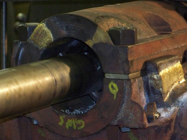
The cutting tool is nearing the end of the first pass through the cross box. There is not an abundance of cuttings as the first cut in such a situation is very experimental: I prefer to take a light cut the first time through to find and remove the worst of the irregular high spots. Nothing could be worse than getting in a rush, and setting the tool for what at first glance looks to be a reasonable cut, only to find that the old bore is so wild that the cutting tool, clamping fixtures, and machine as a whole is laboring terribly before the first cut is completed. The last thing wanted is for the cross box, or any part being machined, to shift accidentally and possibly ruin it. A partial "air cut" now might just save thousands of dollars in pattern and casting fees.
In this shot the shaft-like "high speed steel" cutter, restrained by two set screws, can be seen quite plainly. To adjust the tool for the next roughing pass, the set screws will be backed off slightly, the cutter advanced approximately 3/32 inch by judicious bumping with a small hammer, and then the set screws will be tightened. By advancing the cutting tool 3/32 inch, 3/16 inch will be removed from the hole during the pass. When approaching finished hole size, the depth of cut is accomplished basically the same way, but a dial indicator is placed against the point of the cutting tool to gage the its adjustment to the thousandth of an inch. With the boring bar in the way, measuring the hole directly was a problem: Everyday inside micrometers would not work, as the bar was in the way, and NO WAY was it going to be removed just for measuring. The problem was solved by adding: distance from the front of the hole to the boring bar + bar diameter + distance from back of the bar to the back of the hole! Problem solved. Remember, this is a low budget affair, but it worked! What is the significance of the yellow "Q" on the thrust surface of the piece? An identification marking evidently put on the matching parts when they were manufactured at the Climax plant 90 years ago! Ever since we took apart the disgustingly filthy cross boxes years ago we have been trying to match up the correct caps with the correct boxes, without great success, due to conflicting marking systems, and not until readying the parts for the present machining process was everything figured out, simply because it had to be! Figure stamps were used by us to mark what we thought were sets, at least as they came off the locomotive. When things got cleaned up a bit, it was found that previous mechanics had applied other marking systems, more than one, to get things to match up, but in many cases their markings did not coincide with ours, or even the other old ones! One plan to match things up was to mate the wear marks on the ends of the caps and boxes, but this did not work universally: sometimes the wear marks matched, yet the machining marks on the other end (still virgin metal) did not match. When previous marking systems were followed, either wear marks did not match, or the virgin surfaces did not match, or both were mismatched. Finally it was discovered that each cross box and cap was marked with random (at least to us) figures or letters imprinted into the shim flats, where the markings would never be "erased" under normal operating circumstances. A great big thanks to the man in Corry that ran the boring mill: You saved our butts. The interesting point that was again reinforced during our trials and errors of matching is the fact that the parts of this locomotive are NOT interchangeable, even though the locomotive did manage to operate with all the very similar parts and pieces mish-mashed together. The entire locomotive was so worn that oversized bearing holes allowed mismatched bearings and caps to work, well, sort of! Photo by Christy McDowell FINAL COMMENTS All four of the cross boxes that needed boring have been completed. As of this date 5/10/10 the bronze bearings are being poured at the foundry. |