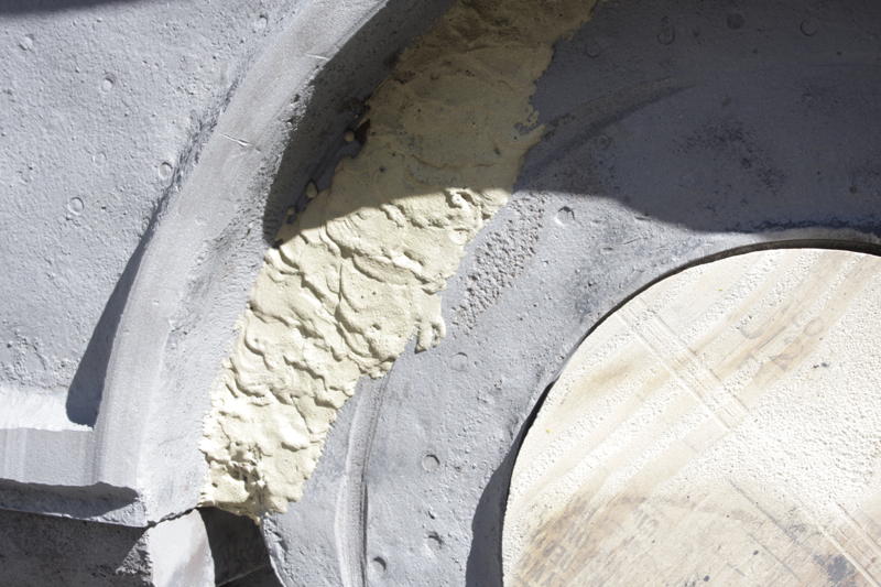
Left engine frame. Note how sloppy this brazing is compared to the similar repair performed on the right engine frame. Did different welders do these two repairs? Likely we shall never know. The groove between the brazing and the plywood circle was produced by some projection on the inner face of the crankshaft disk accidentally rubbing where it was not intended. The depressed surface being protected by the plywood was originally a raised boss (look carefully and one can see the remaining vestiges of the edge of the long missing boss) that acted as a thrust bearing to prevent the crankshaft from migrating towards the right side of the locomotive, due to forces created by the crank shaft and miter shaft gears working against each other. When the crankshaft was removed, another, now removed braze repair was discovered: the cast iron thrust boss was already long gone, and the area had been, at some unknown date, built up proud by the application of several layers of bronze brazing material, which was itself almost worn entirely away. What bronze remained was easily peeled off with a chisel. We will fasten a machined bronze plate to this area to keep the gears and crankshaft in the proper location. Photo by Chad Thompson.
|


